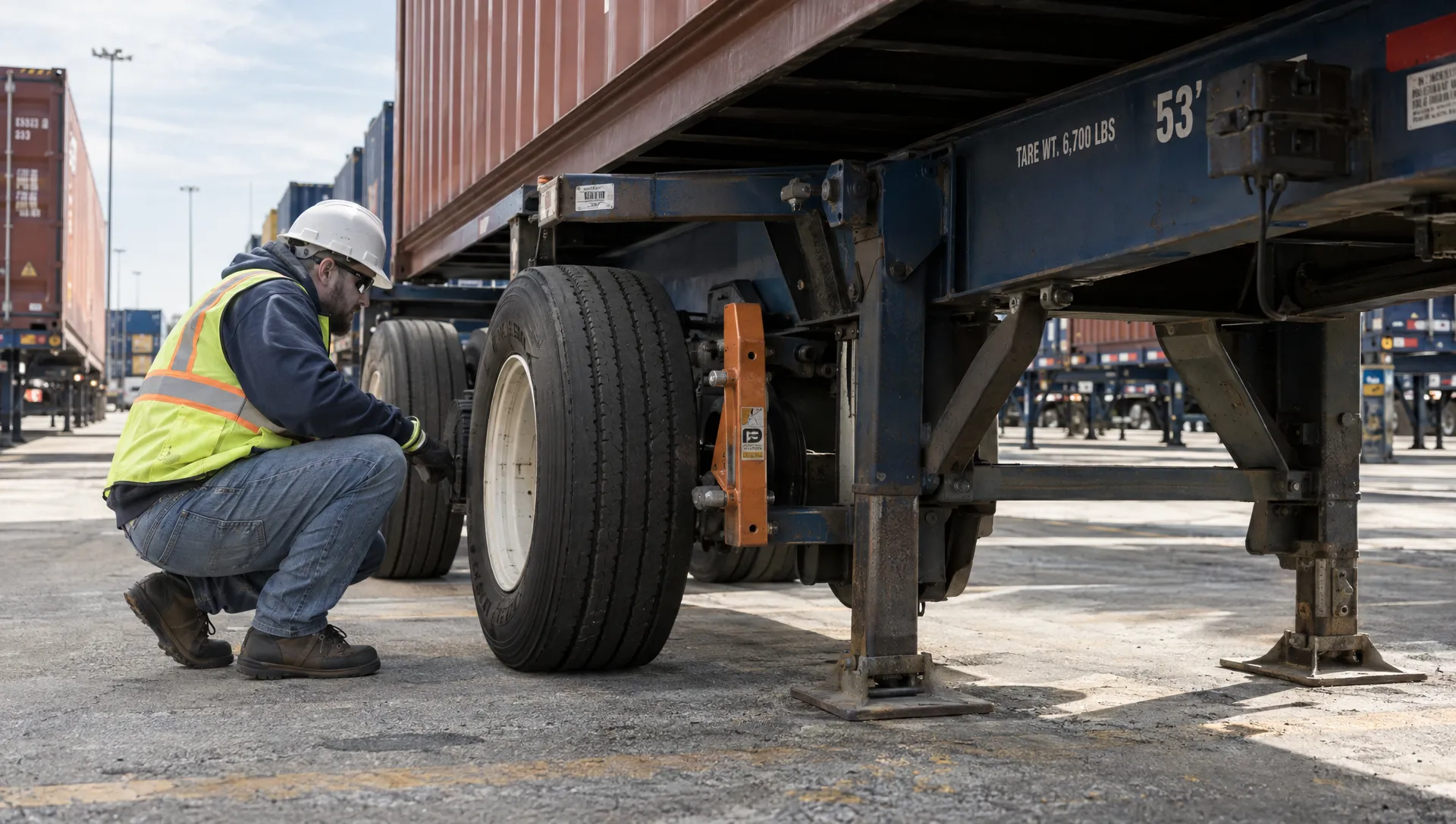
Heavy Haul Load Securement for High-Center-of-Gravity Cargo

For tall transformers, process vessels and industrial skids, heavy haul load securement must address overturning as well as sliding. A shipment can satisfy an aggregate working load limit calculation yet remain vulnerable because its center of gravity, support footprint or restraint geometry was never verified.
The release decision should connect five items: verified cargo data, trailer configuration, directional restraint capacity, route conditions and inspection responsibilities. For logistics directors and EPC teams, the objective is not simply to obtain a securement photograph. It is to establish a defensible transport configuration that the carrier can execute, inspect and maintain throughout the move.
Establish the actual center of gravity and support footprint
Start with the cargo's as-shipped condition, not its operating configuration or preliminary purchase-order weight. Obtain the shipping drawing, verified weight, three-dimensional center-of-gravity location, approved support zones and rated transport attachment points. Include installed accessories, shipping frames, fluids and temporary bracing in that assessment.
The effective support footprint is the area through which the cargo actually bears on its supports. It is not necessarily the skid's outside dimensions. Narrow saddles, elevated feet or an offset internal mass can produce a much smaller stability margin than the packaging suggests.
A simple screening calculation illustrates why heavy haul load securement requires more than chain counting. For an idealized, unrestrained rigid load with a centered mass on level supports, the lateral tipping threshold is approximately:
Lateral acceleration divided by gravity = support width ÷ (2 × center-of-gravity height above the support plane).
An 8-foot support width and a center of gravity 10 feet above that plane produce a theoretical threshold of 0.4 g, assuming sufficient friction to prevent sliding first. This is not a design approval or a permitted cornering limit. It excludes suspension movement, crossfall, wind, restraint behavior and other dynamic effects.
Treat cargo overturning relative to the trailer and rollover of the combined vehicle as separate engineering checks. Lowering the trailer deck can improve overall vehicle stability without correcting an inadequate cargo support footprint.
Verify heavy haul load securement against federal rules
For U.S. highway movements, check the current 49 CFR 393.102 performance requirements. The regulation distinguishes breaking-strength and working-load-limit performance criteria. Its breaking-strength cases include 0.8 g forward deceleration, 0.5 g rearward acceleration and 0.5 g lateral acceleration, applied separately.
These values are not permission to load components beyond their applicable ratings. For cargo not fully contained by the vehicle structure, also address the regulation's downward-force requirement, equivalent to at least 20% of cargo weight.
Federal cargo securement requirements are only one part of dispatch approval. Verify each jurisdiction's applicable rules, oversize or overweight permit conditions, bridge restrictions and route-specific operating requirements. A permit may control speed, travel windows, escorts or weather exposure without approving the securement design.
The route review should also identify adverse crossfall, tight turns, abrupt grade transitions and uneven site access. Dimensional clearance alone does not establish stability through those locations. Where necessary, have the carrier and qualified engineer establish maneuver-specific controls rather than assigning a generic reduced speed.
Apply the correct cargo-specific provisions
The four-tiedown rule is not universal. 49 CFR 393.130 applies to heavy vehicles, equipment and machinery operating on wheels or tracks that individually weigh 10,000 pounds or more. It requires at least four tiedowns and restraint against movement in the specified directions, with attachment arrangements meeting the section's requirements.
A stationary transformer or process skid does not become wheeled machinery simply because a forklift loaded it. Determine which commodity-specific provisions apply, then address the general requirements, including the applicable minimum tiedown count under 49 CFR 393.110.
Heavy haul load securement therefore needs a cargo classification decision before anyone selects a standard chain layout. Length-based minimum counts, machinery-specific requirements and an engineered anti-tip arrangement answer different questions. Meeting one does not automatically satisfy the others.
Calculate aggregate WLL without overstating capacity
Under 49 CFR 393.106, the aggregate working load limit of the tiedowns securing an article or group of articles must be at least one-half its weight. The counting method depends on the tiedown arrangement.
A tiedown running from a vehicle anchor to a cargo attachment point contributes one-half its WLL to the aggregate calculation. A tiedown passing through, over or around cargo and returning to the same side also contributes one-half. A qualifying arrangement passing through, over or around cargo to an anchor on the opposite side contributes its full WLL.
For example, an 80,000-pound unit requires at least 40,000 pounds of aggregate WLL. Eight direct tiedowns, each with a documented assembly WLL of 10,000 pounds, contribute:
8 × 10,000 × 0.5 = 40,000 pounds of aggregate WLL.
For heavy haul load securement, that result establishes only the aggregate-WLL threshold. It does not prove sufficient resistance in every direction, adequate overturning restraint or acceptable loading at the attachment points.
Rate the complete load path. Chain, binder, hooks, connectors, cargo lugs and trailer anchors must all be suitable for the loads and loading directions involved. A higher-rated chain cannot upgrade a lower-rated anchor or make an unrated lifting eye acceptable for transport restraint.
Pro-Tip: Require the securement worksheet to show both the installed device WLL and its contribution to aggregate WLL. Confusing those figures can materially overstate compliance.
Engineer the geometry, blocking and bearing interfaces
Tiedown geometry determines how tension becomes longitudinal, lateral and vertical restraint. A chain that looks substantial may provide little useful resistance in the critical direction. There is no universal tiedown angle that makes every tall load safe.
The engineering review should assess the actual attachment coordinates, allowable lug loading directions, trailer-anchor capacities and overturning moments about the effective support edges. Account for off-center mass and verify that proposed restraints do not overload the shipping frame or concentrate force into a thin enclosure panel.
Blocking and bracing need a similarly complete load path. Establish how longitudinal stops, lateral stops, saddles and their connections transfer force into suitable trailer structure. Loose timber placed beside a skid is not equivalent to a designed stop. Do not assume deck boards, stake pockets or convenient crossmembers can carry the required reactions.
Heavy haul load securement must also preserve bearing conditions. Check local deck capacity, contact pressure, dunnage compression and resistance to support migration. Use friction assumptions supported by the actual interface condition, including contamination, moisture and the suitability of any friction material.
Select devices for the application rather than nominal strength alone. Rated chain may suit heavy steel machinery, while webbing requires appropriate protection from cutting, abrasion and incompatible contact surfaces. Neither eliminates the need for verified attachment points and directional calculations.
Assign a release owner and control configuration changes
The shipper should provide reliable cargo information and manufacturer restrictions. The loading team should implement the approved support and handling arrangement. The carrier must confirm the transport equipment and securement system are suitable, while the driver retains applicable inspection and operating responsibilities.
Where engineering review is required, identify who approves the calculations and who may authorize changes. A forwarder's coordination role does not replace the motor carrier's regulatory duties or the engineer's design responsibility.
The release package should connect the shipping drawing revision, weight and center-of-gravity data, trailer identification, securement layout, component ratings, permit references and inspection records. Photographs should show attachment points, support interfaces and any areas that become difficult to access after loading.
A practical heavy haul load securement release process also defines stop-work triggers. Missing center-of-gravity information, an unapproved lug substitution, a damaged anchor or a trailer change should hold dispatch until the responsible parties resolve the issue. Photographing a deviation does not authorize it.
Pro-Tip: Mark approved transport attachment points on the drawing and, where practical, on the cargo. Keep lifting points visually distinguishable from tiedown points unless their dual use is explicitly approved.
When evaluating heavy haul trucking companies, ask how they document substitutions and manage unresolved loading discrepancies, not just whether they own enough chains.
Preserve the engineering basis across modal handoffs
A highway release cannot simply inherit another mode's restraint approval. Vessel lashings, aircraft restraint and road tiedowns encounter different interfaces and operating conditions. Heavy haul load securement must be reassessed when the support arrangement, shipping frame or transport equipment changes.
Operating scope | Information that must survive the handoff |
Ocean freight, FCL and LCL | Retain packing drawings, support restrictions and handling records. Container stuffing or deconsolidation must not obscure damage or changes affecting the subsequent road configuration. |
Air freight, U.S. imports and exports | Preserve frame and attachment limitations through airline handling. For imports, verify the road configuration after airport recovery; for exports, reconcile factory pickup restraints with airline acceptance and handling requirements. |
Port drayage | Confirm the actual chassis or specialized trailer configuration, road-leg restraints and applicable permits. Do not infer highway readiness solely from terminal release or vessel discharge. |
Cross-dock and warehouse staging | Where staging or equipment exchange is necessary, protect approved bearing surfaces and document any relocation of saddles, blocking or cargo within its frame. |
Project cargo and heavy haul | Reconcile the final loaded configuration with axle loading, center-of-gravity assumptions, route controls and the site unloading plan before dispatch. |
For cargo arriving on a flat rack, the ocean lashing and surveyor documentation provides useful evidence, but it is not a substitute for the highway review. Avoid unnecessary handling when the approved configuration can remain intact through the planned transfer.
Use an observable pre-departure inspection checklist
Inspect the installed arrangement against the released drawing, not against memory or a reference photograph from another shipment. Confirm that the loaded configuration still matches the engineering assumptions after crane release, suspension settling and completion of all loading work.
Checkpoint | Required confirmation | Hold condition |
Cargo identity and configuration | Correct unit, shipping revision and installed accessories | Unexplained weight or configuration difference |
Supports and blocking | Correct locations, full bearing and secure connections | Gaps, crushing, movement or unapproved substitutions |
Restraint equipment | Suitable ratings, readable identification where required and acceptable condition | Damaged components or unverified capacity |
Attachments and routing | Correct lugs, anchors, loading directions and protected contact points | Side-loaded fittings, interference or unapproved attachment |
Vehicle and route | Correct trailer configuration, axle-loading verification and applicable permits | Equipment mismatch or unresolved route restriction |
Inspection access | Safe access or an approved means to inspect critical locations | Critical components cannot be adequately checked |
Record the initial condition so later inspections can detect change. Useful evidence includes support alignment, cargo position relative to fixed references and restraint condition. Do not treat an impact recorder's normal reading as proof that the restraints remain adequate.
The pre-departure check for heavy haul load securement should end with a named release decision, a documented exception process and confirmation that the driver has the relevant instructions.
Define en-route inspection triggers and corrective actions
For accessible cargo, 49 CFR 392.9 requires inspection within the first 50 miles after beginning a trip. Subsequent reexamination is required when the driver changes duty status or after three hours or 150 miles of driving, whichever occurs first. Applicable exceptions should be checked against the regulation.
These are regulatory intervals, not a reason to ignore earlier evidence of movement. Add safe inspection opportunities after events identified in the transport plan, such as a severe road shock, an emergency maneuver or an unusually rough site approach.
If tension changes, distinguish normal seating from a changed load path. Investigate support settlement, blocking migration, attachment deformation and cargo movement before simply tightening the same device again. Repeated loss of tension is a reason to stop and resolve the cause.
A damaged device requires a suitable replacement and review of whether the remaining arrangement was overloaded or displaced. If cargo has shifted, isolate the area and obtain qualified recovery assistance. Do not release restraints on an unstable unit or improvise roadside re-rigging.
Effective heavy haul load securement includes a clear recovery communication chain: driver, carrier dispatcher, shipper representative and the responsible technical reviewer. Resume movement only after the configuration is safe, compliant and released through the agreed process.
Pro-Tip: Put the technical escalation contact and approved drawing revision in the driver's trip packet. A generic after-hours number is insufficient if nobody answering can resolve a configuration deviation.
Frequently asked questions
Are four tiedowns enough for high-center-of-gravity cargo? Not necessarily. Four is a minimum under the heavy wheeled or tracked equipment provision when it applies. Other cargo may follow different count requirements, and any arrangement must also satisfy applicable capacity, performance and stability requirements.
Does meeting the aggregate WLL requirement prevent tipping? No. The aggregate calculation does not establish directional restraint or overturning resistance. Heavy haul load securement must also account for center-of-gravity location, effective support width, attachment geometry and route conditions.
Can lifting lugs be used as tiedown points? Only when their suitability for transport restraint is established. A vertical lifting rating does not automatically authorize angled, repeated or multidirectional tiedown loading. Obtain the manufacturer's or qualified engineer's documented approval for the intended use.
How often must the driver inspect the load? For accessible cargo subject to 49 CFR 392.9, inspect within the first 50 miles, then at a duty-status change or after three hours or 150 miles of driving, whichever occurs first. Use additional checks when conditions warrant.
Need to coordinate a high-center-of-gravity shipment? Shipit Logistics can support end-to-end project cargo execution or a standalone heavy-haul, drayage or staging scope. Share the shipping drawings, weight, center-of-gravity data and origin-to-destination requirements so the team can coordinate the appropriate transport planning and technical review.